Accelerated thermal ageing procedures
03. Apríl, 2013, Autor článku: Firický Eduard, Elektrotechnika
Ročník 6, číslo 4  Pridať príspevok
![]() The thermal endurance of insulating materials is essential for use in the selected application, particularly for materials containing the organic compounds. Use of the specific insulation in a particular application must be complying with strict temperature management of electrical equipment. Therefore the insulating materials classification into thermal classes and accelerated ageing procedures to determine their characteristic parameters were introduced. Proposed article mainly deals with the thermal endurance properties and the ageing of electrical insulation. Thermal classes, related materials, ageing temperatures, ageing ovens and other are shown.
The thermal endurance of insulating materials is essential for use in the selected application, particularly for materials containing the organic compounds. Use of the specific insulation in a particular application must be complying with strict temperature management of electrical equipment. Therefore the insulating materials classification into thermal classes and accelerated ageing procedures to determine their characteristic parameters were introduced. Proposed article mainly deals with the thermal endurance properties and the ageing of electrical insulation. Thermal classes, related materials, ageing temperatures, ageing ovens and other are shown.
1. Thermal endurance and ageing
Insulating materials during operation time are exposed to adverse climatic impacts, ambient temperature changes in a relatively wide range and temperature gradient caused by material power losses. Temperature changes affect the mechanical, thermal, electrical and also another physical and chemical properties of the insulating materials. Solid insulating materials properties – mechanical strength and elastic modulus – due to increased temperature detoriate, plastics soften and are easy to damage. At even higher temperatures, these materials transit into liquid state. Electrical properties are then generally worse and electric strength decreases.
By reducing the temperature plastic materials solidify and harden. Despite the fact, that their mechanical strength increases, they are easier to damage as in extent of their optimum operation temperatures, because at the same time their tensibility decreases and become brittle. These properties changes are transient and will pass, when the temperature change will return to its normal value. Permanent changes caused by chemical processes activated by temperature have significant impact to insulating materials properties. By increasing the temperature molecules acquire necessary kinetic energy to initiate chemical reactions and chemical reactions are being accelerated [1]. This process is usually illustrated by change of position in the free energy phase space G, characterized by configuration transformation X, from position X1 to position X2, where energy to overcome energy barrier Gm is supplied by systems increased temperature (Fig. 1).

Figure 1: Double potential well model characterizing the system free energy change during the thermal ageing.
In the organic substances various chemical processes apply that depend on the material type. In general, there are present reactions with oxygen contained in the air or in the material itself. Oxygen reaction mechanism with insulation is based on gradual double bonds disruption. The rate of ageing depends on the material temperature and the surface area on which the material is exposed to the air. One of the possible prevention of atmospheric oxygen oxidation is to prevent access of atmospheric oxygen to material and usage of antioxidants, which work by delaying the start of destructive oxidation. Organic dielectrics depolymerization is another chemical reactions type. In these reactions occur the destruction of polymer chain and its splitting into shorter chains, even the monomers. This change is usually accompanied by release of gases from insulation.
Contradictory to the depolymerization reaction is called polymer chain branching so called crosslinking, increasing the molecular weight. With increasing molecular weight mechanical strength increases, but decreases tensibility – insulation becomes harder and more fragile. The final effect of properties changes depends on the above reactions ratio, depending on the polymer chemical nature together with the reaction conditions and the temperature. The presence of mechanical stresses has affect to crosslinking ratio and degradation speed, affects the crosslinks distribution and thus the structure of crosslinking. In general mentioned thermal ageing effects can be divided into two groups [2]:
- process of chemical and physical changes due to chemical degradation reactions, polymerization, depolymerisation, diffusion, etc.
- thermomechanical impacts caused by forces resulting from thermal expansion and/or thermal contraction.
Accelerated thermal ageing tests conditions are well established analytical techniques to obtain insulation materials thermal endurance characteristics in times significantly shorter, than those required for conventional procedures. The working procedures test techniques provide standards [3-10]. According to these standardized procedures the results of these procedures are thermal endurance curves and parameters used to characterize the thermal lifetime, defined as follows:
- Temperature index (TI): Numerical value of the temperature in degrees Celsius derived from the thermal endurance relationship at a time of 20 000 h (or other specified time).
- Relative temperature index (RTI): The temperature index of a test material obtained from the time which corresponds to the known temperature index of a reference material when both materials are subjected to the same ageing and diagnostic procedures in a comparative test.
- Halving interval (HIC): Numerical value of the temperature interval in degrees Celsius which expresses the halving of the time to end-point taken at the temperature equal to TI.
- Assessed thermal endurance index (ATE): Numerical value of the temperature in degrees Celsius, up to which reference electrical insulating (control) material possesses known, satisfactory service performance in the specified application. The ATE of a specific material may vary between different applications of the material. ATE is sometimes referred to as “absolute” thermal endurance index.
- Relative thermal endurance index (RTE): Numerical value of the temperature in degrees of Celsius at which the estimated time to end point of the candidate electrical insulating material is the same as the estimated time to end-point of the reference electrical insulating material at a temperature equal to its assessed thermal endurance (ATE). Estimate of the endurance of a candidate material, made by thermal ageing simultaneously whit the control material.
- Lifetime characteristics under thermal stress – thermal endurance graph (Arrhenius plot): Graph (Fig. 2). in which the logarithm of the time to reach a specified end-point in thermal endurance test is plotted against the reciprocal thermodynamic (absolute) test temperature
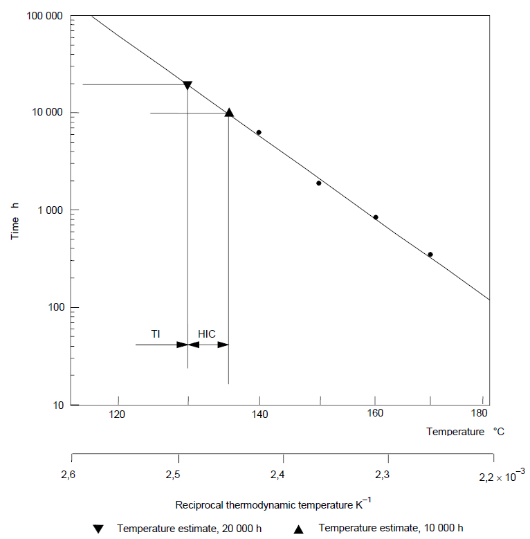
Figure 2: Lifetime characteristic under long-term thermal stress – thermal endurance graph (Arrhenius plot) (according to IEC 60216-1).
Changes of insulating materials properties by the action of elevated temperature have led to idea to divide insulation materials, in terms of their thermal endurance, into groups of approximately the same thermal properties. For each insulation materials group the maximum temperature is assigned, at which they can operate continuously. Some basic thermal classes are used. Thermal classes and their respective temperatures are summarized in Table 1.
Temperature ranges above 250°C are divided by 25°C and are assigned to the relevant classes (275, 300 etc.). If the thermal class describes electrical appliance, usually designates the maximum allowable service temperature corresponding to a given appliance at nominal load and other conditions, so the insulation exposed to the maximum temperature will need to have at least the same thermal endurance as temperature belonging to the appliance thermal class [11].
Table 1: Thermal classes (according to STN EN 60085) and related materials [12].
| ATE or RTE (°C) | Temp. (°C) | Therm. class | Related materials | |
|---|---|---|---|---|
| ≥90 | <105 | 90 | Y | organic materials e.g. paper, wood, cotton, silk together with conventional impregnating compounds (shellac, asphalts, oils), from the group of polymers PVC |
| ≥105 | <120 | 105 | A | organic materials e.g. paper, wood, cotton, silk, fabric together with a suitable impregnant or enamel, cellulose based synthetic materials, press boards for electrical purposes, paper-based adhesive tapes, acrylate combined with paper, PET foil with caoutchouc, PES fabric or tape, hardened cotton fabric with phenolic resin |
| ≥120 | lt;130 | 120 | E | organic materials e.g. cellulose or hardened paper, hardned fabric, cellular tissue in combination with impregnants or phenol-formaldehyde or phenolic resin, hardened paper and fabric with phenol formaldehyde, pressed phenol-melamine laminate, PET foil with electrical press boards |
| ≥130 | <155 | 130 | B | inorganic materials e.g. glass fibers, glass laminate with epoxy binder, mica based inuslation, PES resin with glass mat, PET/caoutchouc and PET/acrylate based adhesive tapes |
| ≥155 | <180 | 155 | F | components of these materials are glass fibers, mica paper, PET, PEN foils, aramid and its modifications (nomex, kevlar, twaron), aramid paper, epoxy and novolac resins |
| ≥180 | <200 | 180 | H | silicone and modificated epoxy resin is used as a binder, aramids, polyimids, PES, mica, mica paper and its modification (remca, samica, calmica) and its composites |
| ≥200 | <220 | 200 | N | glass, asbestos (banned), aramid papers with silicone binders, teflon, polyester-alkyd based impregnating enamel |
| ≥220 | <250 | 220 | R | same as class N materials, glass fibers, asbestos (banned), aramid papers mostly with silicone bindings, aromatic polyamide |
| ≥250 | <275 | 250 | 250 | polyimides (kapton), aramids (nomex), PTFE, class R materials with new binding materials, polyimid foils |
2. Accelerated thermal ageing tests
To describe the accelerated ageing test procedures must be chosen for at least three elevated temperatures. The lowest temperature has to be chosen in order to achieve failure point after at least 5 % of expected insulation system service lifetime. The other two higher temperatures are to be selected in 20 K intervals. When more than three test temperatures are necessary, can be used 10 K intervals. Preferred ageing temperatures are given in Table 2 [2]. For some electrical insulation materials the maximum test temperature has to be lower than the transition point (e.g. fusion, boiling etc.). The standardized procedure for the evaluation of the thermal properties of a material consists of a sequence of steps, as follows [3]:
- Preparation of suitable specimens appropriate for the intended property measurements.
- Subjecting groups of specimens to ageing at several fixed levels of elevated temperature, either continuously, or cyclically for a number of periods between which the specimens are normally returned to room temperature or another standard temperature.
- Subjecting specimens to a diagnostic procedure in order to reveal the degree of ageing. Diagnostic procedures may not be non-destructive or destructive determinations of a property or potentially destructive proof tests (e.g. applied AC voltage test).
- Extending the continuing heat exposure or the thermal cycling until the specified end-point, i.e. failure of specimens or a specified degree of change in the measured property, is reached.
- Reporting the test results in a way depending on the kind of ageing procedure (continuous or cyclic) and diagnostic procedure (see under item c)): ageing curves, or time or number of cycles to reach the end-point, for each specimen.
- Evaluating these data numerically and presenting them graphically.
- Expressing the complete information in abbreviated numerical form by means of the temperature index or halving interval.
Each test procedure should specify the shape, dimensions and number of these test specimens, the temperatures and exposure times, the property to which TI is related, the methods of its determination, the end-point, and the derivation of the thermal endurance characteristics from the experimental data.
| Service temperature [°C] | 55 | 75 | 90 | 105 | 120 | 130 | 155 | 180 | 200 | 220 | 250 |
|---|---|---|---|---|---|---|---|---|---|---|---|
| Thermal class | (55) | (75) | Y | A | E | B | F | H | N | R | (250) |
| Ageing temperatures[°C] | 135 | 155 | 170 | 185 | 200 | 210 | 235 | 260 | 280 | 300 | 330 |
| 125 | 145 | 160 | 175 | 190 | 200 | 225 | 250 | 270 | 290 | 320 | |
| 115 | 135 | 150 | 165 | 180 | 190 | 215 | 240 | 260 | 280 | 310 | |
| 105 | 125 | 140 | 155 | 170 | 180 | 205 | 230 | 250 | 270 | 300 | |
| 95 | 115 | 130 | 145 | 160 | 170 | 195 | 220 | 240 | 260 | 290 | |
| 85 | 105 | 120 | 135 | 150 | 160 | 185 | 210 | 230 | 250 | 280 | |
| 75 | 95 | 110 | 125 | 140 | 150 | 175 | 200 | 220 | 240 | 270 |
To characterize the material behavior at its long-term thermal stress are required different endurance data depending on selected attribute and the selected end-point value to facilitate the right material selection for a particular use in the insulation system. There are two alternative ways to define the end-point value:
- As a percentage increase or decrease in the measured value of the property from the original initial state. This approach will provide comparisons of materials, but does not include relationship of the property value required in normal operation, as is the case b). Therefore, the actual numerical value from test in the original material state should be stated.
- As a fixed value of the chosen property. This value might be selected with respect to usual service requirements. End-points of proof tests (in cyclical ageing) are therefore stated in most cases as a fixed values of the property (e.g. electrical strength).
The chosen property should reflect, in a significant fashion if possible, a function of the material in practical use. A choice of properties is given in [4]. By standard [4] to provide uniform conditions, the conditioning of specimens after removal from the oven and before measurement may need to be specified. Specimens shall be conditioned by exposure to the lowest level of ageing temperature of the test for two days (48 h ± 6 h). If the test specimens size or the specimens forms are dependent on the temperature exposure, then test methods that are not depend on these effects shall be used. If material specifications are available, property requirements in terms of acceptable lower limits of TI values are usually given. If such material specifications are not available, a selection of properties and methods for the evaluation of thermal endurance is given in [3].
For detructive and non-destructive tests, for each exposure temperature and for each heat ageing period, the value of the chosen property is plotted as a function of the logarithm of the time (Figure 3). The point at which this graph intersects the horizontal line representing the end-point criterion is taken as the time to failure. The end-point, limit value should be chosen so that describes the insulating material deterioration degree, which reduces the insulation system ability to withstand stresses occurring in the normal use. The degree of deterioration, which is herein referred as threshold tested value, should be close to allowable material properties safe value, which is required in practice. The accuracy of endurance test results depends largely on the number of specimens aged at each temperature. Instructions for an adequate number of specimens are given in [5].
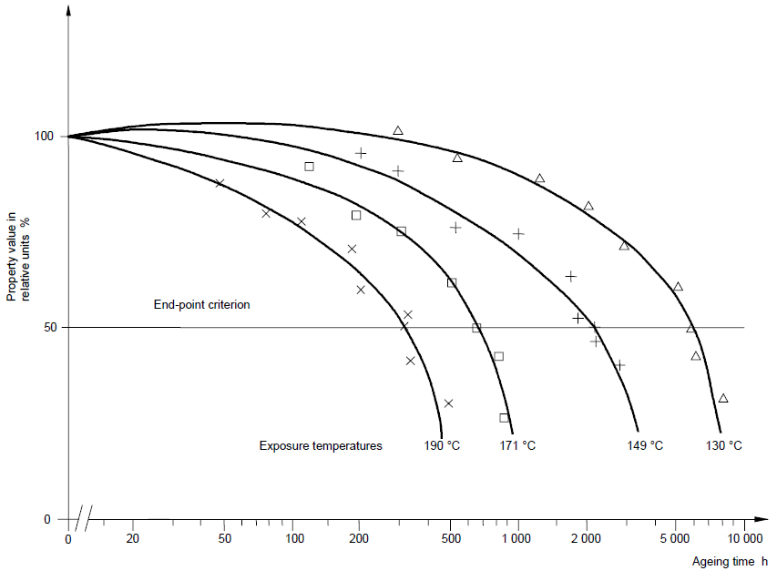
Figure 3: Determination of the time to reach the end-point at each temperature – property variation (according to IEC 60216-1)
For selection of temperatures and exposure times apply different rules. As mentioned above, to determine TI should be specimens exposed to at least three, however preferably four temperatures, which cover wide enough temperature range to establish Arrhenius relationship between the times to reach threshold value for a given material and reciprocal thermodynamic (absolute) temperature. Determination of the relative temperature endurance, i.e. estimate the thermal endurance of tested material is based on two objectives and are as follows:
- To exploit an assumed relationship between thermal endurance and service performance, and to use this to predict a value for a preliminary assessment of service temperature of a material for which there is relatively little service experience (by comparison with a known reference EIM)
- To improve the precision of a thermal endurance determination by reduction of systematic errors in the ageing process. If, after ageing, the results for the reference EIM are found to be significantly different from earlier experience, this may indicate changes in material or equipment. This may be investigated and possibly corrected. In any case, the simultaneous ageing of reference and candidate will at least partially compensate for systematic changes.
RTE has been introduced in the updated standard [10] to reduce systematic errors in the TI determination. Thermal endurance profile (TEP) has been deleted in order to established HIC without confusion RTE calculation is based on data obtained by TI calculation. From thermal endurance data obtained for reference (control) material is determined the time, at which is TI equal to the known value – a correlation time. From thermal endurance data obtained for test (unknown) material is TI in correlation time caluclated. This value is searched RTE [12].
3. Ageing ovens
In this paper we describe required parameters for ventilated and electrically heated single-chamber and/or multi-chamber ovens for thermal endurance evaluation of electrical insulation based on standards [6-8]. IEC standard [6] covers the minimum requirements for ventilated and electrically heated single-chamber ovens, with or without forced gas circulation, for thermal endurance evaluation of electrical insulation. It covers ovens designed to operate over all of part of the temperature range from 20 K above ambient to 500 K. Next appropriate standard [7] covers the minimum requirements for precision ovens for thermal endurance evaluation of electrical insulating materials and other appropriate applications. It covers ovens designed to operate over all or part of the temperature range from 20 K above room temperature up to 300 K.
Last standard for ageing ovens [8] covers the minimum requirements for ventilated and electrically heated multi-chamber ovens used for thermal endurance evaluation of electrical insulation and of any other appropriate thermal conditioning application where the use of single-chamber ovens is inappropriate. It covers ovens designed to operate over all of part of the temperature range from 20 K above ambient to 500 K. It gives acceptance tests and in-service monitoring tests for both unloaded and loaded multi-chamber ovens and conditions of use.
Definitions
- Rate of ventilation N: Number of air changes per hour in the exposure chamber at room temperature that indicates how many times per hour the oven replaces air; regulated with ventilation opening apertures.
- Temperature fluctuation: The maximum change in temperature at one point in the exposure volume over a perion of time. It depends on factors such as the sensitivity and type of regulation – on/off, proportional – and the weight of heating element in proportion to surface area.
- Temperature difference: Maximum difference of temperature between any two points in the exposure volume at any one time. Depends on the temperature uniformity of heating elements, their placement in the oven and how the air circulates.
- Temperature variation: Difference between the highest temperature and the lowest temperature measured in the exposure volume over a period of time.
- Temperature deviation: Calculated difference in the exposure temperature from the intended value due to the combination of the temperature difference, temperature fluctuation and the error in the measurement of temperature.
- Time constant: Measure of time taken for the temperature of a standard specimen to approach the exposure volume temperature, the rate of speed at which the standard specimen is heated from room temperature to any oven temperature. It is the main parameter of oven, which affects the rate of specimen temperature increase is the air circulation inside oven.
The test methods and service requirements
The oven chamber has to be made of suitable materials and all electrical and other auxiliary elements have to be easily accessible for maintenance. Inner oven part should be constructed of suitable anti-corrosion material, which has no absorption properties. All joints have to be leak-proof and not to corrode. Interior surfaces must be easy to clean. The oven door and front of oven chamber must be capable of being closed with enough downforce in order to closure be tight. If it is necessary, oven closure should have sealing, the inside of the oven be reliably separated from the atmosphere, when the doors are closed. Ovens should have safety device that turns it off, when the temperature inside the oven significantly rises above the set temperature, preventing accidental loss of experimental date and specimens (emergency thermostat).
Rate of ventilation:
Rate of ventilation is determined by measuring the additional power required to oven chamber with opened air vents to keep the set temperature, compared to the case, when the oven is maintained at the same temperature with all vents closed. The oven chamber is tested at these temperatures:
- 100°C,
- at the maximum temperature at which the oven chamber will be used.
There is need to seal all the air vents, doors, openings for thermometers and specifically where the ventilator shaft enters in the oven. Electricity consumption meter (watt-hour meters) with a resolution of 1.0 kWh or more accurate is necessary to connect to oven electrical supply. The oven chamber is heated to the test temperature. Measure the ambient temperature at distance of 2 m from the oven, approximately of the oven air inlet at least 1 meter from any solid object. When the oven temperature stabilizes, measure the power consumption for a period of time, such as half an hour.
All sealer elements are then removed, the input and output vents are estimated partially open in order to achieve the desired rate of air exchange. Measure the power consumption for about half an hour, the same way as before. If necessary, change the ventilation opening apertures position and measurement is repeated until the required air exchange rate is reached. The rate of ventilation is calculated by the following equation:
T_a}{V_0(T-T_a)}") |
(1) |
where N – the rate of ventilation, P1 – mean power consumption in [W], of the non-ventilated oven, obtained by dividing the energy consumption, E1 [Wh], determined from the Wh-meter reading by duration of test, in hours, P1=E1/t1 [hod], P2 – mean power consumption in [W], of the ventilated oven, dividing the energy consumption, E2 [Wh], determined from the Wh-meter reading by duration of test, in hours, P2=E2/t2 [hod], V0 – volume of the test chamber [dm3], Ta – is the mean ambient temperature [K], T – is the exposure temperature [K]. Rates in the range 5 to 20 changes per hour shall be made available through the exposure chamber.
Temperature change:
Nine thermocouples is placed into the empty oven, composition of iron-constantan or chromel-alumel, made from wires with a diameter of 0,5 mm, while wires connection should not be longer than 2,5 mm; the ventilation openings and apertures are set to achieve the desired air exchange from 5 to 20 times per hour. Eight thermocouples are placed into the eight oven corners at a distance of 50 mm from the wall. The ninth thermocouple is placed at the geometric center of oven. At least 300 mm thermocouple wire must be inside the oven to reduce the conduction heat dissipation from the thermocouple.
The oven chamber is then heated to the maximum operating temperature, fixed for a minimum of 16 hours. During the one complete thermal cycle the temperature of all nine thermocouples is measured with an accuracy of 0.1 °C. Sufficient number of measurement is made, so during one cycle is possible to determine the maximum, the minimum and the average temperature of each thermocouple. During this measurement the ambient temperature does not vary by more than 10 °C and the oven supply voltage does not vary by more than 5%. Then the arithmetic mean value of nine thermocouples data is calculated with accuracy of 0,1 °C. This value is recorded as set-up oven temperature.
Table 3: Allowed temperature deviation values for single and multi-chamber ovens (according to STN EN 60216-4-1 and to STN EN 60216-4-3).
| Temperature range [°C] | Temperature variation [°C] |
|---|---|
| up to 80 | 4 |
| 80 – 180 | 5 |
| 180 – 300 | 6 |
| 300 – 400 | 8 |
| 400 – 500 | 10 |
Then the difference between the highest and the lowest temperature is calculated. This data variation is written as an indication of temperature. It should not exceed the values given in the Table 3. The oven chamber is then maintained at the same temperature for 120 hours. The temperature and the supply voltage should be at this time in mentioned limits, once a day is measured temperature variation. It should not exceed the values given in Table 3. Oven set temperature value is designated during each step of the measurement. The maximum adjusted temperature deviation should not exceed the given values.
Time constant:
Provide a standard specimen consisting of a solid brass cylinder of diameter (10 ± 0,1) mm and (55 ± 0,1) mm long to which one junction of a differential thermocouple has been soldered. Raise the oven temperature to 200 °C or its maximum designed temperature, whichever is the lower, and allow it to stabilize. Allow the standard specimen to stabilize at ambient temperature for at least 1 hour.
The heating elements are then switched on, if it is possible, turn off the ventilator and the door is opened to 90 degrees. The standard specimen is then quickly hung vertically to oven geometric center. Heat-resistant cord with a maximum of 0,25 mm diameter is used. The free end of the thermocouple joint should be hung at a distance of 80 mm from the standard specimen. The door left open for (60 ± 2) s, then close door and the temperature difference is recorded every 10 seconds until a maximum change has been established. Continue recording every 30 seconds until the temperature difference has dropped below 10 % of the maximum. Plot the values recorded against time in second.
The maximum temperature difference is divided by 10 and record as T10. Record as the time constant the time in seconds, taken from the plot of temperature difference versus time, for the temperature difference to pass through a maximum and decrease to T10. The time constant should not be greater than 600 s.
During the accelerated thermal ageing tests and determining the RTI have the both materials, i.e. reference and candidate, be placed together in the same oven. The different (i.e. separate) oven chambers can be used for tests when the suitable tests established comparable results. If it is suspected, that the degradation products of one material can have a negative impact on the others surface (i.e. when the two materials are not the same type), they should not be aged simultaneously in the same oven. In this case attention should be given to the fact, that both ovens have the same air change characteristics, work with the same air speed and at the same temperature.
References
- LEWIS, T.J.: Ageing – A Perspective, IEEE Electrical Insulation Magazine, Vol. 17, No. 4, pp 6-16, July/August 2001.
- STN EN 60505. Hodnotenie a klasifikácia elektroizolačných systémov. 2012.
- STN EN 60216-1: Elektroizolačné materiály. Dlhodobá teplotná odolnosť. Časť 1: Postupy starnutia a vyhodnotenie výsledkov skúšok. 2002.
- STN EN 60216-2: Elektroizolačné materiály. Dlhodobá teplotná odolnosť. Časť 2: Stanovenie dlhodobej teplotnej odolnosti elektroizolačných materiálov. Výber skúšobných kritérií. 2006.
- STN EN 60216-3: Elektroizolačné materiály. Dlhodobá teplotná odolnosť. Časť 3: Inštrukcie na výpočet charakteristických hodnôt dlhodobej teplotnej odolnosti. 2006.
- STN EN 60216-4-1: Elektroizolačné materiály. Dlhodobá teplotná odolnosť. Časť 4-1: Teplovzdušné sušiarne na skúšky starnutia. Jednokomorové sušiarne. 2006.
- STN EN 60216-4-2: Elektroizolačné materiály. Dlhodobá teplotná odolnosť. Časť 4-2: Teplovzdušné sušiarne na skúšky starnutia. Presné sušiarne na použitie do 300 °C. 2001.
- STN EN 60216-4-3: Elektroizolačné materiály. Dlhodobá teplotná odolnosť. Časť 4-3: Teplovzdušné sušiarne na skúšky starnutia. Viackomorové pece. 2001.
- STN EN 60216-5: Elektroizolačné materiály. Dlhodobá teplotná odolnosť. Časť 5: Určenie relatívneho indexu dlhodobej tepelnej odolnosti (RTE) izolačného materiálu. 2008.
- STN EN 60216-6: Elektroizolačné materiály. Dlhodobá teplotná odolnosť. Časť 6: Stanovenie teplotných indexov (TI a RTE) izolačného materiálu použitím metódy pevne určených časov. 2007.
- STN EN 60085: Elektrická izolácia: Tepelná klasifikácia a označovanie, 2008.
- MENTLÍK, V. Dielektrické prvky a systémy. Praha: BEN – Technická literatúra, 2006. ISBN 80-7300-189-6.
Coauthor of this paper is Michal Váry, IPAEE DMaT FEI STU Bratislava, Ilkovičova 3,812 19 Bratislava

