Simulations of Induction Machine Behaviour
17. Júl, 2013, Autor článku: Heretík Peter, Elektrotechnika
Ročník 6, číslo 7  Pridať príspevok
![]() The main purpose of this document is to examine properties of electrical machines. Calculations and simulations are aimed to an asynchronous motor. For calculations and simulations are used data of this machine provided by real manufacturer as an input for program ETAP. Results from ETAP are evaluated in tables or graphically and compared to values provided by manufacturer or to manual calculations based on equations characterizing the behaviour of induction machine. Dynamic calculations in this document describe basic equations of induction motor, the behaviour of induction motor at the starting and after connecting a static load to the grid while the motor is running at its rated speed.
The main purpose of this document is to examine properties of electrical machines. Calculations and simulations are aimed to an asynchronous motor. For calculations and simulations are used data of this machine provided by real manufacturer as an input for program ETAP. Results from ETAP are evaluated in tables or graphically and compared to values provided by manufacturer or to manual calculations based on equations characterizing the behaviour of induction machine. Dynamic calculations in this document describe basic equations of induction motor, the behaviour of induction motor at the starting and after connecting a static load to the grid while the motor is running at its rated speed.
1. Introduction
Examination of properties of induction motor is based on simulations in program ETAP. Basic equations of induction motor are verified according to rated values from manufacturer. Motor acceleration analysis is demonstrated in the context of given motor load characteristic in program ETAP. Simulation from ETAP is compared to manual calculation and to the values provided by manufacturer. An equation for calculating motor torque is used in case when a static load is connected to the power source after the motor has started and reached its rated speed. In this simulation, the generator in scheme is substituted by a power grid, by the reason of frequency, which is influenced by the generator after connecting a static load.
2. ETAP
ETAP (Electrical Transient Analyzer Program) is the most comprehensive analysis platform for the design, simulation, operation and automation of generation, distribution and industrial power systems. ETAP is developed under an established quality assurance program and is used worldwide as a high impact software. It is completely localized in four languages with translated output reports in six languages. As a fully integrated enterprise solution, ETAP extends to a Real-Time Intelligent Power Management System to monitor, control, automate, simulate, and optimize the operation of power systems [1]. ETAP offers a suite of fully integrated software solutions including arc flash, load flow, short-circuit, relay coordination, cable ampacity, transient stability, optimal power flow, voltage drop and more [2].ETAP’s quality assurance is specifically dedicated to meeting the requirements of:
- ISO 9001:2008 Standards
- United States Code (U.S.C.) Title 10 CFR 50, Appendix B
- United States Code (U.S.C.) Title 10 CFR 21
- ANSI/ASME N45.2-1977
- ASME NQA-1 (Incl. Subpart 2.7)
- ANSI/IEEE 730.1-1989
- CAN / CSA-Q396.1.2-1989
- ANSI N45.22-1972 [2]
3. Parameters of induction motor
Parameters of motor used for dynamic calculations in following chapters of this document are real data from manufacturer of specific electrical machine. These parameters are provided by manufacturer in datasheet, a document summarizing these parameters. A typical datasheet of induction motor contains information about rated values (voltage, power, speed, frequency, torque etc.), critical values which can not be exceeded or underrated (breakdown torque, minimal starting voltage). An example of induction motor electrical data is in Tab. 1.
| Description | Unit | Value |
|---|---|---|
| Component identification Code | - | RCV5130POM |
| Manufacturer | - | SCHORCH |
| Serial number of motor | - | 44047811 |
| Rated power | kW | 480 |
| Rated voltage Ur/ connection | kV | 10 / star |
| Minimal starting voltage | % Ur | 80 |
| Rated speed | rpm | 2975 |
| Rated frequency | Hz | 50 |
| Rated efficiency | % | 95 |
| Efficiency at: | ||
| 3/4 load | % | 95 |
| 1/2 load | % | 94,5 |
| Rated power factor cosφ | - | 0,90 |
| Power factor at: | ||
| 3/4 load | 0,88 | |
| 1/2 load | 0,84 |
A torque/speed characteristic, supplied by manufacturer, is also necessary for dynamic calculations in following chapter. An example of current-torque/speed characteristic is in Fig. 1. Values from manufacturer are used in program ETAP for Transient stability and Motor acceleration analysis.
4. Dynamic calculations
For Transient stability and Motor acceleration analysis in ETAP was used scheme in Fig. 2. In this scheme an asynchronous motor and a static load are supplied by power from a synchronous generator.
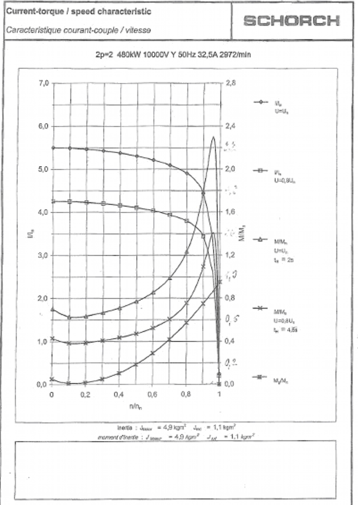
Fig. 1. Current-torque/speed characteristic [4]
4.1. Basic equation verification
To gain the most accurate results is needed to verify values of rated power, voltage and current provided by manufacturer. Some of these values (e.g. rated current) are calculated according to rated voltage, power, power factor or efficiency by program ETAP with a smaller or bigger deviation from the values in datasheet. Electrical power of an induction motor, also called input, is the power supplied into the machine from the source. This power is spread in the machine into losses in the rotor winding and the mechanical power on the shaft, consequently used for driving other machinery. The ratio between the electrical and mechanical power of induction machines, is the efficiency.
 |
(1) |
where Pe is electrical power and Pm is mechanical power.
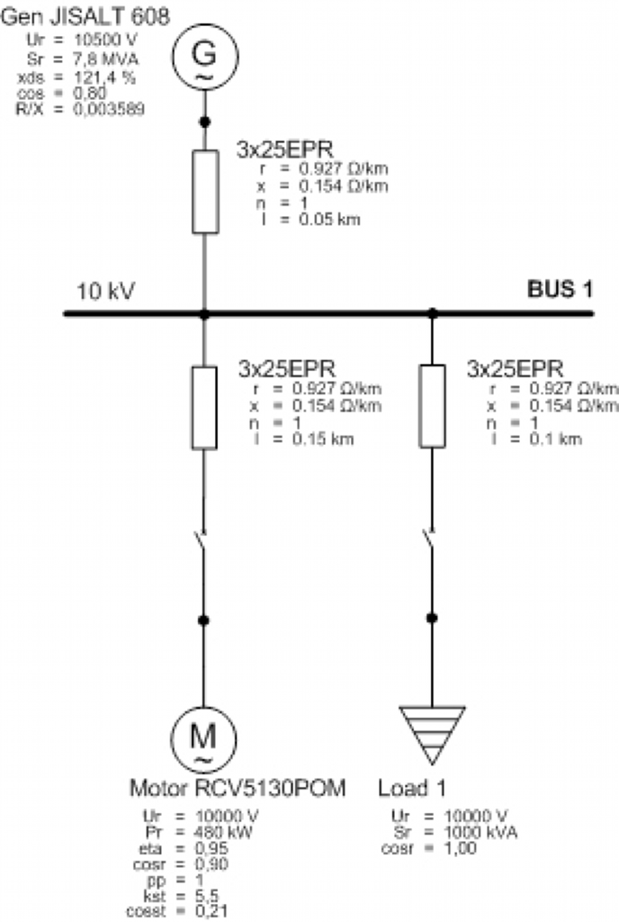
Fig. 2. Simulation scheme
Basic equations for calculating electrical and mechanical power for asynchronous motor are in following equations:
 |
(2) |
 |
(3) |
where T is torque, ω is angular velocity and n is speed. Rated values provided by manufacturer are in Tab. 2.
Tab. 2. Rated values
| Unit | Value |
|---|---|
| Pr | 480 kW |
| Ur | 10 kV |
| Ir | 32,5 A |
| nr | 2975 rpm |
| cosφ | 0,9 |
| η | 0,95 |
| Mr | 1540 |
| Connection | Y |
Rated values were used to calculate apparent power S and slip s in following equations.
 |
(4) |
 |
(5) |
 |
(6) |
 |
(7) |
 |
(8) |
 |
(9) |
Comparing the value of rated mechanical power and the result of equation (4) can be seen a small deviation which can be negligible. Slip calculated in (9) equals to slip calculated by ETAP.
4.2. Motor acceleration calculation
One of the most important values at starting an induction motor is the starting time at rated voltage Ur and rated load. Values should be provided by manufacturer in datasheet. Starting time provided by manufacturer of the motor used in Fig. 2 is 2 seconds. This time can be estimated from time dependence of speed in program ETAP. Time dependence of speed, terminal current and terminal voltage calculated by ETAP is in Fig. 3.
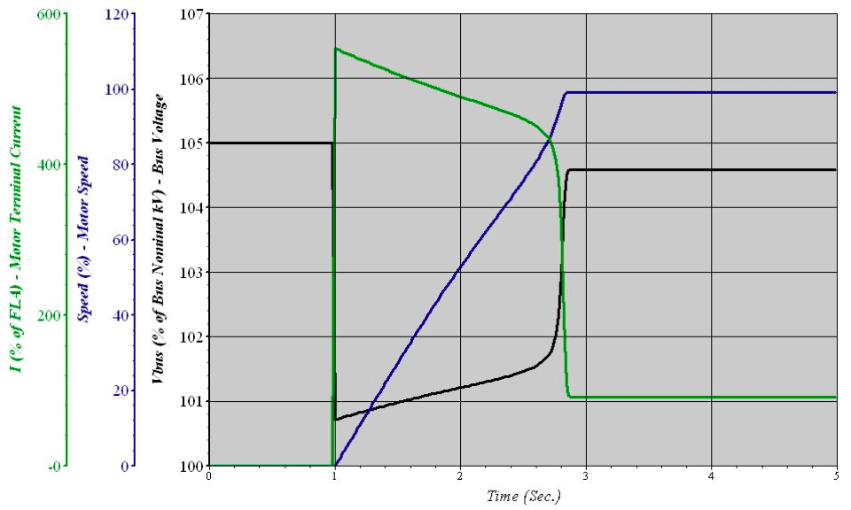
Fig. 3. Time dependence of current, speed and voltage
In Fig. 4 is detailed view of time dependence of the speed of the motor, which shows the time, when the motor reaches its rated speed.
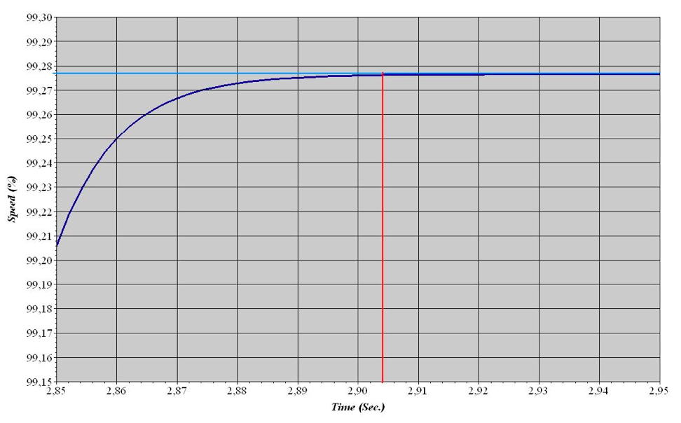
Fig. 4. Detailed time dependence of speed
In Fig. 3 can be seen that the motor was started in 1 second. From Fig. 4 can be taken the time when the motor reached its rated speed, which is 2.904 seconds. The result of subtracting these two values, 1.904 seconds, is the starting time of the motor calculated by program ETAP. Starting time can be calculated manually from motor torque/speed characteristic with motor torque and load torque curves. For calculation is needed acceleration torque curve, which is the result of subtracting motor torque and load torque curves, both provided by manufacturer. The starting time can be calculated from following equation:
 |
(10) |
where J is moment of inertia of motor and driven machine from datasheet, Ma is motor acceleration torque and Δω is angular velocity of the motor. Moment of inertia J is provided by manufacturer in the datasheet. For motor used in Fig. 2, the moment of inertia value is J=6 kg.m2.
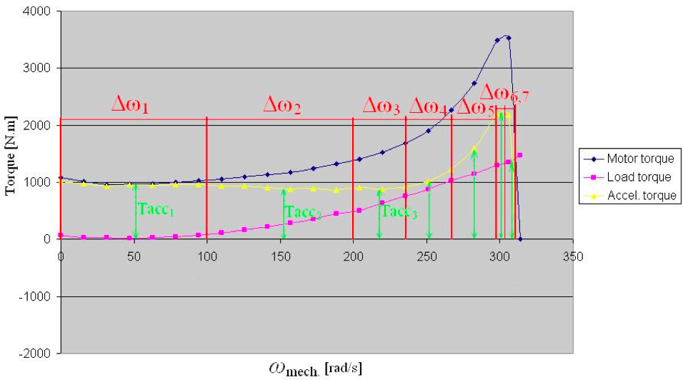
Fig. 5. Acceleration time calculation
Fig. 5 shows the angular speed dependence of torque of the induction motor used in Fig. 2, which was created manually according to curves provided by manufacturer. The curve of acceleration torque is divided into n sections where can be the curve interpolated by straight line and the mean value of torque for each interval Δωn is used to calculate the acceleration time in specific interval. Following equation represents the calculation for the first interval:
 |
(11) |
Dividing the curve of acceleration torque into more sections means more accurate results, but also more arduous calculation. The result of sum of all partial times is the acceleration time of the induction motor.
 |
(12) |
The starting time calculated manually is 1.857 seconds. It is clear, that both of starting times are smaller than the time provided by manufacturer, which means that the motor will accelerate in less than 2 seconds at rated voltage and rated load. A deviation between calculated acceleration time and the time taken from ETAP simulation is 0.047 seconds. Considering that the motor is powered by a generator with rated voltage 10.5 kV used in electrical grid in Fig. 2, the starting time calculated by ETAP could be smaller than the time provided by manufacturer.
4.3. Motor torque equation
A torque of the motor is directly proportional to square of voltage and inversely proportional to square of frequency. For induction machine is valid following equation:
^2") |
(13) |
where M is motor torque, f is frequency and U is voltage, all at the same time. Following equation was verified on case that a static load is connected to the Bus 1 in Fig. 2 while the motor is running at the rated speed.
^2 \left ( \frac{f_1}{f_2} \right )^2") |
(14) |
The frequency is directly proportional to revolutions of the generator powering all loads.
 |
(15) |
where p is number of pole pairs, n is speed of the generator in rpm. After connecting a load, revolutions and the frequency of generator decrease. A device used to regulate the speed of the machine is called governor. Considering the governor as a device which affects the speed of the generator and consequently the frequency, verifying the equation (13) would be very difficult. For that reason, equation (13) is simplified to case when the motor and the static load are powered by a power grid keeping the frequency at constant value. This scheme is in Fig. 6.
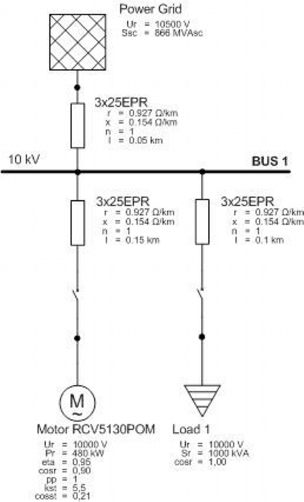
Fig. 6. Simulation scheme with power grid
Simplified equation for motor torque is following:
^2") |
(16) |
For this calculation was used an option of Motor Acceleration Analysis in ETAP. In 1 second was started an induction motor and in time of 10 seconds is connected a static load to the Bus 1 in Fig. 6. A more detailed time dependence of motor torque and motor bus voltage during connecting a passive load is in Fig. 7.
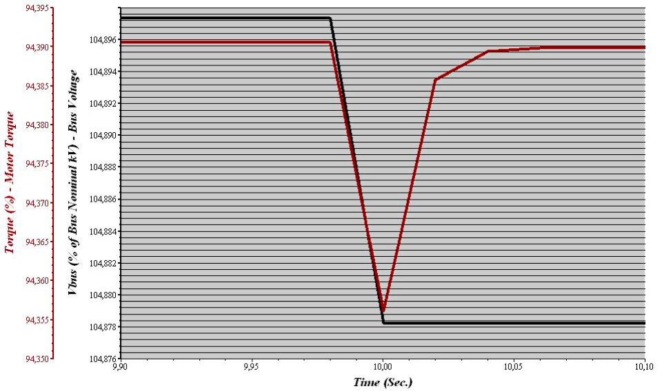
Fig. 7. Time dependence of motor torque and bus voltage
Voltage and torque drop to lower value in time when the static load is connected to the Bus 1. Values in equation (16) marked with index 1 were taken from Fig. 7 in time before connecting the static load when a torque and voltage were constant. Values marked with index 2 were taken at the time of 10 seconds.
Tab. 3. Values estimated from Fig. 7
| U1 [% of Ur] | 104,8973 |
| M1 [% of Mr] | 94,3905 |
| U2 [% of Ur] | 104,8782 |
| M2 [% of Mr] | 94,356 |
The reason why the value of voltage is higher than the rated value is that the generator in Fig. 2 is rated on 10.5 kV. Motor torque M2 can be calculated using values from Tab. 3 in equation (16).
^2 = 94,3561") % of Mr % of Mr |
(17) |
In equation (17) is calculated motor torque at the time the static load is connected to the Bus 1 in Fig. 6.
5. Conclusion
Values in equations in chapter 4.1 were calculated according to rated values given by manufacturer. Values from manufacturer can be rounded, what could be a reason of a small deviation between these and calculated values. A value of calculated slip at rated speed is equal to calculation in ETAP. In conclusion of calculating acceleration time of asynchronous motor can be shown, that manual calculations are correct according to calculations from ETAP and a deviation between them, which was 0.047 seconds, can be assumed as negligible.
An equation (13) for motor torque in 4.3 describes the constant ratio of torque, voltage and frequency before connecting a static load and at the time the load is connected. Calculating of motor torque at connecting a static load in simplified equation (16) was with a negligible deviation according to value taken from time dependence simulated by ETAP. This small deviation between calculated value in (17) and the value M2 in Tab. 3 estimated from Fig. 7 can be caused by inaccurate determining values from the graph in Fig. 7. This deviation can be negligible. In further studies of induction machines will be determined voltage ratios of individual motors and a group of motors at the starting, impact of the reactance of the transformer and generator on voltage drop at starting of asynchronous motors, eventually the short circuit analysis of induction motors.
Acknowledgements
Research described in the paper was supported by AREVA NP Controls, s.r.o.
References
- ETAP Operational Technologz, INC., ETAP 11.0.0, Product overwiev, B8-PO-E11-0911-15
- ETAP for electrical power systems, ONLINE HELP, 18.03.2013,
http://etap.com/index.htm - Hruškovič L., Elektrické stroje, Bratislava: Vydavateľstvo STU, 1999, 497p., ISBN 80-227-1249-3
- Electrical data provided by SCHORCH, Motor data sheet
- Electrical data provided by JEUMONT Electric, Generator data sheet
Coauthors of paper are Marián Halaj and Róbert Maier.

