Impact of the PVE on quality of electricity in the distribution system
29. Január, 2014, Autor článku: Viglaš Dominik, Elektrotechnika
Ročník 7, číslo 1  Pridať príspevok
![]() The quality of electricity may be assessed based on two aspects, namely the quality of supply and voltage quality. The quality of supply means above all reliability of supply of electricity. The voltage quality is assessed according to the characteristics defined in the standard EN 50 160. The trend of increasing the share of RES leads to efforts to connect a large number of these sources to the distribution system. With the increasing number and installed capacity is becoming increasingly difficult to find a suitable location and condition in the distribution system that would allow make a construction and connection. [1] This paper deals with impact of photovoltaic power plants (PVE) on the distribution system and possibilities for reducing the effects on the voltage conditions in the low voltage system.
The quality of electricity may be assessed based on two aspects, namely the quality of supply and voltage quality. The quality of supply means above all reliability of supply of electricity. The voltage quality is assessed according to the characteristics defined in the standard EN 50 160. The trend of increasing the share of RES leads to efforts to connect a large number of these sources to the distribution system. With the increasing number and installed capacity is becoming increasingly difficult to find a suitable location and condition in the distribution system that would allow make a construction and connection. [1] This paper deals with impact of photovoltaic power plants (PVE) on the distribution system and possibilities for reducing the effects on the voltage conditions in the low voltage system.
1. Introduction
Many factors affect the quality of electricity. One of them is connecting and operation of renewable energy sources (RES). Requirement of the Distribution System Operator is to adapt the RES operation to the distribution system operation and do not affect the conditions in the distribution system. Requirements for electricity producers are defined in the Technical Conditions of the Distribution System Operator that are based on the standard EN 50 160. The standard sets limits for high quality power supply. The most frequent adverse effects with which the customer can meet in terms of quality of supply are the voltage fluctuations, therefore short-term increase of voltage, voltage dips and any subsequent interruption of supply voltage. [2]
Current trends in power engineering are focused on the development of RES so there is increasing the pressure to maintain the voltage quality on the customers side. This problem requires a solution in terms of legislative measures as well as technical solutions. The quality of electricity may be assessed based on two aspects namely the quality of supply and voltage quality. The voltage quality is assessed according to the characteristics defined in the Standard EN 50 160. The most frequent adverse effects with which the customer can meet in term of quality of electricity are the voltage fluctuations, therefore short – term increase of voltage, voltage dips and many subsequent interruption of supply voltage. Current trends in power engineering are focused on the development of renewable energy sources, so there is problem requires a solution in terms of legislative measures.
2. Legislative framework
General view of the legislation can be divided by scope of activities that market participant carries. All levels of legislation define the necessary activities and processes for the electricity producers, transmission system operator, distribution system operators, electricity suppliers and customers. On 1 January 2005 came into effect two laws that in the Slovak Republic created new energy legislation. These include Act. No. 251/2012 Coll on Energy and consequential amendments and Act. No. 250/2012 Coll on Regulation in Network Industries and on amendments to certain acts. The main purpose of the preparation and adoption of the above laws has been transpose into the Slovak energy legislation an European directives which govern this issue. These laws are the first level of the legislative framework of quality of electricity. Act. No 251/2012 Coll defines the basic processes in the energy sector [3], rights and obligations of the market participants, from electricity producers, transmission and distribution system operators and customers.
According to § 17 of the Act No. 251/2012 Coll electricity customer has a right to conclude a contract with the electricity supplier which must include the method and amount of compensation for failure to comply of the quality of electricity. It also has a right to supply electricity of the required quality. One of the most important part of energy legislation in the field of quality of electricity is Regulatory Office for Network Industries (RONI) Decree No. 275/2012 laying down a quality standards and defines the standards of transmission and distribution of electricity. Another equally significant level of legislative framework of the quality of electricity is an Operating Rule of distribution system operators and technical conditions for connection to the distribution system. The purpose of the Operating Rule is transparent and non – discriminatory manner to lay down the rules concerning the legal relations that arise between the distribution system operator and the other market participants. [4] The figure 1 shows the hierarchy of legislation in terms of quality of electricity in the Slovak Republic.
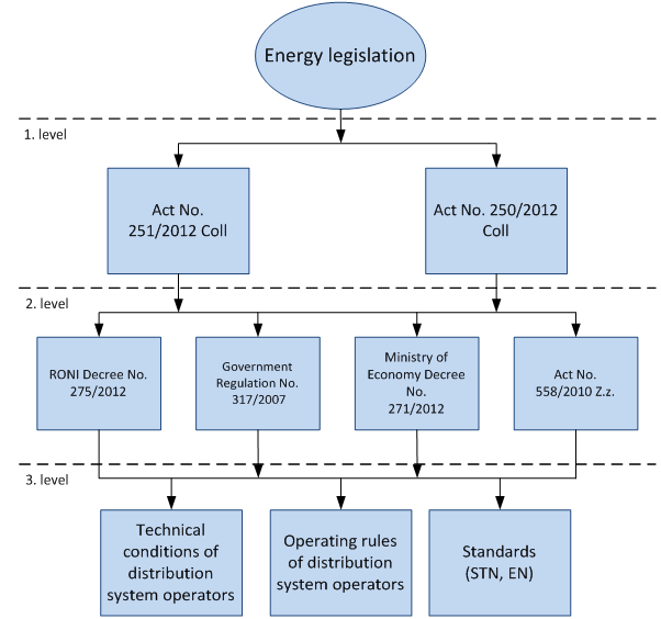
Fig. 1 Legislative framework of quality of electricity in the Slovak Republic
Slovak Republic was incorporated into European trend of liberalization of the energy sector. The common routing of electricity sector directly concerns the Slovak Republic. Representative of European legislation in the field of quality of electricity is a Directive 2009/72/EC of the European Parliament and of the Council concerning common rules for the internal market in electricity which repealing Directive 2003/54/EC. [5] The aim of the European internal market in electricity is to give to consumers a choice between different electricity suppliers and access the market for all suppliers, but especially for smaller ones who invest into renewable energy sources. [6]
3. Technical conditions of the distribution system operator
Technical conditions are for all participants a binding document that specifies the minimum technical and operational requirements for connection the device to generate electricity such as photovoltaic devices. The operation of each production affects the voltage quality in distribution system. According to the technical conditions is the voltage change a maximum difference between the supply voltages at any point in the network before and after manipulation. Voltage change can be caused for example by connecting large loads, for example motors, transformers, capacitors etc. The basic criterion for assessing of connectivity is the increased voltage caused by the operation of production, which in the worst case may not exceed:
 |
(1) |
for the common supply point (110 kV and 22 kV). Another important criterion for assessing the connectivity such as PVE is a voltage change while connecting and disconnecting of PVE.
 |
(2) |
The most important parameters negatively affecting to the voltage quality in the distribution system is also flicker which is most frequently crossed voltage parameter in the distribution system. It is defined as rapid changes of voltage in electricity grid which is reflected as changes of the intensity of light. Maximum allowable voltage changes are dependent on the frequency of their occurrence as specified in PNE 33 3430-0. Rapid voltage changes are mainly due to rapid changes of load which requires high reactive power from the grid and therefore causes voltage sags on the impedance. This problem is particularly marked in networks with high impedance.
![P_{lt} = \sqrt[3]{\sum_{n=1}^{12} \frac{p_{stn}^3}{12}}](http://s0.wp.com/latex.php?latex=P_%7Blt%7D+%3D+%5Csqrt%5B3%5D%7B%5Csum_%7Bn%3D1%7D%5E%7B12%7D+%5Cfrac%7Bp_%7Bstn%7D%5E3%7D%7B12%7D%7D&bg=ffffff&fg=000000&s=0 "P_{lt} = \sqrt[3]{\sum_{n=1}^{12} \frac{p_{stn}^3}{12}}") |
(3) |
Plt is essential for voltage quality. Permissible value which can be produced by all production facilities in a worst case is Plt = 0,46. Critical are mainly wind power plants, on the other side, installations with inverters decreases a flicker.
4. Impact of pve on the distribution system
It is necessary to restrict the effect of local production due to disturbed devices of customers and facilities of the Distribution System Operator. Possible disturbance depends on the amplitude, frequency and duration of the effects on the network and also on the extension of certain operating funds. It is also necessary to take into account the currently operating assets factor. [7] We can divide the negative effects in generally into:
- Local impacts – the impact on the network to which is the PVE connected. It cannot be completely eliminated and assess the acceptable limit is under the study for network connectivity,
- System impacts – the impact on the system as a whole. There are caused by issued with the prediction of production, integrating into daily load diagram.
Not negligible impacts on the distribution system are also economic impacts. The main obstacle for the production of electricity form PVE is a need to regulate the uneven supply. It is expensive, because of the large installed capacity grows demands for support services, especially for secondary and tertiary regulation. This fact as well as lack of funds for investment is now a critical issue for further development of RES. The local impacts are manifested mainly as voltage changes, harmonics and the deterioration of power factor. Extend of the impact of RES can be distinguished according to the using and the nature of power and also to the type of generator connected to the network.
4.1 Impact of the capacity factor
Capacity factor is a tool used to compare a different energy sources. Expresses the equivalent period during which the source operates with a total installed capacity per year. In this way is recalculated total operating time of the device with variable power moving from 0 to 100 % on the equivalent period during which the source operated with 100 % load. The equivalent time expressed in hours per year divided by the total time of the year reflects a capacity factor. The PVE capacity factor is calculated 9,7 % to 11 % that mean a operating time at full output from 850 to 1000 hours per year.
4.2 Impact of the operation of PVE on amplitude and on the change of voltage phase shift
The size of impact on voltage affects mainly the short-circuit power at the coupling point. In addiction this value affects on the voltage at the coupling point the supplied power and the impedance between the source coupling point and supply coupling point. For the power supply to the distribution system have to the source increase the voltage at the coupling point of the value it needs to compensate of voltage drop between the coupling point and supply coupling point. This voltage is given by impedance between source coupling point and point of consumption, by the transmitted power.
It is important to note that each source of active and reactive power contributes to the rising of voltage in the distribution system, which may cause approaching the maximum allowable voltage which do not contribute an illegal increase of voltage according the standard EN 50 160. [8] The impact on the change of voltage phase shift has mainly the flow of current through the inductive reactance character device. In the low voltage distribution system the inductive reactance contributes to the total impedance of fifty percent which implies that the value of the voltage angle in distribution system can be influence with a active power.
4.3 Impact of the PVE on the operation of distribution system
Voltage tolerances in a low voltage distribution system are heavily influenced by the operating voltage in the medium voltage distribution system. Suppose that the operation of PVE connected to the medium voltage network will cause the maximum permissible voltage increase by 2 % UN by the Technical Conditions of the Distribution System Operator. Consider the state of the network with low voltage supply. The aim is to determine the theoretical value of the voltage at the end of the line, where we can except a voltage drop shown at the Fig.2.
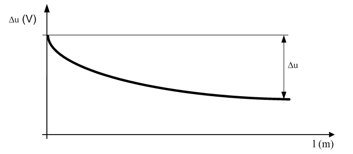
Fig. 2 The voltage drop at the end of the line
In the input of the distribution transformer we have voltage 23,54 kV. We used a distribution transformer 22/0,42 kV with + 5 % transformer tap on the primary side. Parameters of low voltage network are follows:
- low voltage line length is 600 m,
- AlFe42 used with parameters: R1 = 0,867 Ω, L1 = 9,234e-4 H/km,
- load – 15 kW.
The voltage at the end of the low voltage network was calculated with iterative method with an accuracy of 1 V.
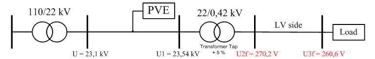
Fig. 3 Voltage in a low voltage network with the load and distribution transformer 22/0,42 kV (transformer tap + 5%) with a connected PVE in the medium voltage network
By the Fig. 3, it is clear that at low voltage side of distribution transformer (that the node U2f) was created increased phase voltage 270,2 V, respectively 117 % UN (> 110 % UN) according to standard EN 50 160. At the end of the line voltage 260,6 V was established, which is the voltage drop from the beginning of the line of 4,15 %. In both nodes we observe the illegal voltage increase.
Tab. 1 Possible network configuration and settings of the transformer 22/0,42 kV
| Low voltage network with a load, medium voltage network with PVE, transformer 22/0,42 kV | ||
|---|---|---|
| CASE | U2f (V) | U3f (V) |
| U = 23,1 kV; U1 = 23,54 kV Central tap | 258,7 | 248,6 |
| U = 23,1 kV; U1 = 23,54 kV Transformer tap + 5 % | 270,2 | 260,6 |
| U = 23,1 kV; U1 = 23,54 kV Transformer tap – 5 % | 247,1 | 236,6 |
| U = 21,7 kV; U1 = 22,14 kV Central tap | 244 | 233,3 |
| U = 21,7 kV; U1 = 22,14 kV Transformer tap + 5 % | 255,5 | 245,4 |
| U = 21,7 kV; U1 = 22,14 kV Transformer tap – 5 % | 232,4 | 221,2 |
Tab. 1 shows the possible network configurations, In this case it record the voltage in low voltage network with a load 15 kW, with distribution transformer 22/0,42 kV. In one case there was an illegal voltage increase at the end of the low voltage line particularly when the excepted voltage on the primary side of the transformer 23,54 kV with transformer tap + 5 %.
3. The possibilities of reducing the impact of pve on voltage in low and medium voltage network
In order to maintain the stability of such a complex system like a power system, it is necessary to regulate a voltage that is one of the main parameter of the system. Due to increasingly higher number of the RES in the power system, respectively in the distribution system occurs to some extent influence the voltage regulator system and it is necessary to provide these equipments with a regulation of reactive power because the regulation of reactive power flow is one option of regulation of voltage. Another option to eliminate the impact of PVE is deployment of distribution transformers with remote control.
3.1 Reactive power control options
For the most connected PVE is a requirement to comply a neutral value of the power factor. Balance of reactive power must be considered especially in term of the operation mode. The operating system is based on the annual use of production that counts in the range 850 – 1000 hours per year. It follows that the most of the time is PVE operated with minimum active power. In the case of low active power flows it doesn´t need a neutral power factor due a reactive power through transformers, lighting and so on. Relatively small reactive power compared to the large installed capacity of PVE cannot be underestimated therefore it is necessary to embed the appropriate compensation device.
It often happens that the balance of reactive power in the coupling point makes a capacitive character which is caused by long lines in the PVE. In this case there is a unsolicited supply of capacitive reactive power to the system. Therefore it is necessary to pay a special attention to the balance of reactive power in PVE. In terms of impedance is a PVE a RC circuit with specific values of inductive and capacitive reactance. Due to the reactance is realized supply, respectively consumption of reactive power which has a role in terms of power factor. In terms of the needs of dispatching control of the power factor is a regulation of reactive power relative to the size of the active power.
A very important aspect in terms of the balance of reactive power is operations of PVE at a time out of generate electricity. This mode of PVE is a very important in terms of balance of reactive power. One possible reactive power control is the use of installed photovoltaic inverters. Their use for this purpose depends on their construction. Very often is using of inverters for regulation of reactive power certain with additional technical changes. The problem with this type of regulation may be the size of current reserves of inverters to regulation of reactive power. Inverters were originally designed for maximum active power so only 5 % increasing of current may be very problematic when is inverter full load with active power. [9]
Another option for the regulation of reactive power is the static compensative devices (capacitors and inductors). The compensation device can be connected to a low and medium voltage network. The advantage of this solution is relatively low loss in installed capacitors. In addition to space requirements is another disadvantage stepped principle of regulation. Probably the most optimal technical solution is the hybrid reactive power regulators. The base is the few degrees of capacitors and inductors and parallel connected inverter. It combines the active and passive method of generating the reactive power. Due to the combination of active and passive regulation was achieved a reduction of investment and operating costs partly, due to the reduction of the losses of device. The hybrid regulator is optimized in terms of maintaining the lowest possible losses of passive elements. Due to its properties it may be part of smart grid ensuring compliance with the requirements for connecting distributed resources in the distribution system. It regulates the reactive power in the specific range and communicates with the control system by defines standards.
3.2 Deployment of distribution transformers with remote control
Standard distribution transformers (22/0,42 kV and 22/0,4 kV) allow adjustment of output voltage by changing transformer taps in the non-load condition. This contributes a restriction on the distribution of electricity to customers who are supplied from this transformer. Elimination of restrictions on the distribution of electricity and voltage increased represents a transformer with remote control taps under the load. Assume the same scenario as in Fig. 2 with a change of transformer taps to – 2,5 %.
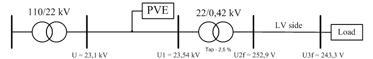
Fig. 4 Voltage in a low voltage network with the supply and distribution transformer 22/0,42 kV (transformer tap – 2,5%) with a connected PVE in the medium voltage network
The Fig. 4 shows that due to the influence of reducing the required voltage output with the tap changing there is an elimination of illegal increase of voltage. Effect of PVE is observed not only on the voltage level in which is installation performed (in our case medium voltage level) but at a lower voltage level (in our case low voltage level). The operation of any production device affect on the voltage quality (increasing of voltage). Technical Conditions defines the maximum values of increasing of voltage but only on the voltage level with connected PVE.
As a result of our analysis, voltage ratios are in the allowable limits sets by the Technical Conditions on the medium voltage level with connected PVE that does not cause increased voltage according to standard EN 50 160 (> 110 % UN). The analysis also shows that a greater impact of PVE is observed in the low voltage network and the size of impact depends on many parameters and configurations, either on its own generating device or individual elements of the system. For this reason it is necessary to address the issue of the impact of PVE on a lower voltage level especially in terms of compliance of voltage at the end of low voltage line.
4. Conclusion
The issue of operation of renewable energy is very extensive and current. Due to the stepwise connection of another RES will grow a number of networks with unsatisfactory, respectively with reduced quality of electricity. It is important that further connection of RES will implemented according to the rules which reduce the impact on the customers and on the distribution system.
5. Acknowledgements
This work was done during implementation of the project Effective control of production and consumption of energy from renewable resources, ITMS code 26240220028, supported by the Research and Development Operational Program funded by the ERDF.

References
- TLUSTÝ, Josef – ŠVEC, Jan – SÝKORA, Tomáš. 2010. Vybrané problémy připojování a provozu OZE v dostribučních soustavách. In Proceedings of the Conference ČK CIRED 2010. Tábor, 2010.
- STN EN 50 160:2011, Voltage characteristics of electricity supplied by public electricity networks.
- Act No. 656/2004 Coll. on Energy and consequential amendments
- ZSE distribučná, a.s.. 2011. Prevádzkový poriadok prevádzkovateľa distribučnej sústavy. [online]. 2013 Available on:
http://www.zsdis.sk/sk/O-spolocnosti/Prevadzkovy-poriadok - LOPEZ, Rodrigo – GLACHANT, Jean-Michel – PÉREZ, Yannick. 2008. A framework for Quality Regulation in Electricity Distribution. 978-1-4244-1744-5/08/$25.00 ©2008 IEEE
- Directive 2009/72/EC of the European Parliament and of the Council concerning common rules for the internal market in electricity
- WEIDONG, Yang. 2010. Impact of Large Scale and High Voltage Level Photovoltaic Penetration on the Security and Stability of Power System. In Proceedings of the Power and Energy Engineering Conference (APPEEC) 2010, Chengdu, ISBN 978-1-4244-4813-5.
- VACULÍK, Petr – NOVOTNÝ, Josef. 2011. Nové poznatky a zkušenosti s dispečerským řízením OZE připojených do DS. In Proceedings of the Conference ČK CIRED 2011. Tábor, 2011. ISBN 978-80-905014-0-9.
- HOLOUBEK, Jiří. 2012.Fotovoltaické elektrárny a jalový výkon. In Proceedings of the Conference ERU 2012. Brno, 2012. ISBN 978-80- 260-3431-5.
Co authors of this paper are Beláň, A., Cintula, B., Slovak University of Technology in Bratislava, Faculty of Electrical Engineering and Information Technology, Institute of Power and Applied Electrical Engineering, Ilkovičova 3, 812 19 Bratislava 1

