Search of semiconductor components using non-linear junction detector (NLJD)
29. August, 2014, Autor článku: Rejdík Martin, Elektrotechnika
Ročník 7, číslo 8  Pridať príspevok
![]() The purpose of this paper is introducing NLJD detector, it’s functions and familiarization with physical principles, on which is using non-linear junction detector based on. Describe separate parts of NLJD, parameters and counting power RF loss on certain parts of the system.
The purpose of this paper is introducing NLJD detector, it’s functions and familiarization with physical principles, on which is using non-linear junction detector based on. Describe separate parts of NLJD, parameters and counting power RF loss on certain parts of the system.
Introduction
The threat of a company or individual to be illegally eavesdropped is today much bigger than ever before. The spy bugs and other surveillance devices were in the past much less available than today. In relative terms, electronic espionage is easy, widespread and driven by seemingly endless financial incentives for those who choose to cross the line on behalf of others. Surveillance devices are on high technological level today and there is many physical principles and technologies how they can work. Most sophisticated eavesdropping devices can work in passive mode where minimum or none transmitting radio signals which could be detected by standard methods or radio spectrum analyses. One of the methods how to search inactive and passive devices without radio transmitting signals is using Non- linear junction detector.
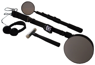
Fig.1 Picture of NLJD
1. Non linear junction detectors – general usage
Non-linear junction detectors (NLJD) are devices designed for search and detection of different types of covert listening devices, various electronic appliances and transmitters comprising of semiconductors. Detectors are capable of detecting almost any electronic appliance in any operational mode: active, stand-by, switch-off. The designation of such devices consists in detection of radio microphones, microphone amplifiers, dictaphones in premises (walls, floors, ceilings, furniture, etc.). NLJD got a reputation as perfect means of counter-espionage, as embassies and other diplomatic posts are known to be most popular targets for eavesdropping equipment. Some specific models of NLJD are used by the police in search for weapons during events involving great masses of people. Detectors are used for providing location secure from covert listening devices in different organizations.
Non-linear junction detectors can serve multiple purposes and have a wide range of implementation, starting from ground detectors up to equipment used for detection of mobile phones. Wide range of NLJD is presupposed by the type of material or surface for search operations – ground detectors are preferable for object detection in soil, portable detectors tuned to appropriate frequency are better in search within wooden furniture. [4]
2. Structure of NLJD and principle
It is important to understand basic physical principle of semiconductor detection using NLJD and to know from which individual part is device build.
2.1 Structure of NLJD
All the NLJD detector has very same construction – basic functional blocks which are described here:
- Transmission module -Tx (transceiver) generates the transmission frequency 863MHz (1st.harmonic wave)
- receiving module – Rx (receiver) receives 2nd and 3rd harmonic wave frequencies which further filters, modulates, processed, and display on the screen. IT also enable audio listening partial frequencies to specify measuring results.
- Diplexer module – is used to separate the signal transmitting and receiving parts which allows us to use a single antenna for both transmission and receiving
- Tx antenna module – has at surveyed detector NR-900EMS circular polarization. Indeed, mostly used NLJD antenna today is with circular polarization, which can be either right-handed or left-handed. The advantage may be that the antenna can be accurately directed to the place that we want to explore. Curl has a helical shape, rotates about its axis. When are the circularly polarized waves reflected, they also changes rotation in the opposite direction, which remove of spurious signals that are reflected in the area several times. The antenna can receive signals that go straight through and are reflected twice but you already have a lower signal level and so we can recognize them.
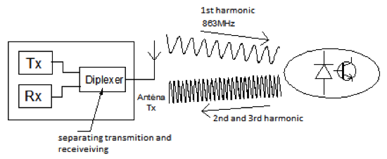
Fig.2 Description of detection and principle
2.2 Principle of detection
Transmitting section generates a pulse signal of a frequency 863 MHz, which is transmitted from the antenna to the space. Posted the first harmonics after reflection from the semiconductor or metal changes the frequency. After reflection from the semiconductor is converted to the second harmonic (1726 MHz). After reflection from the metal to the third harmonic (2589 MHz). The receiving part filters all the received signals and waits until antenna captures 2nd or 3rd harmonic frequency. These are the capture of receiving further processed. The output is then the value of the signal level 2nd and 3rd harmonic imaging on a scale of digital displays and the possibility of these higher harmonics as well as listen to audio through headphones.
3. Basic technical parameters
3.1 Operating frequency
NLJD detectors mostly transmits in the range of 800-1000 MHz. The frequencies are transmitted from the transmitting part and usually the manufacturer is trying to vote in such frequencies to avoid interference with mobile phones and other devices operating at similar frequencies. The detectors can be divided into detectors with a fixed frequency, which is still used to detect the same frequency. There may be a problem, if the detector is used at the point where the operating frequency of The detector uses yet another device, there may be interference between these devices and the measured values can then be distorted. There may be interference from mobile phones, a growing number of wifi networks and other wireless systems. This problem may occur mainly in large cities, where is increased probability of wireless systems operating on similar frequencies. Another group of detectors are devices using a range of frequencies and they are able to tune in to another frequency if such interference by other signals .. most of these detectors offer the option of manual or fully automatic tuning system frequency. Furthermore, they may offer special search modes which varies the frequency and may thus try to recognize false PN junctions at different frequencies.
3.2 Transmission power
The radiated power is most often ranges from tenths to tens of watts. However, it is important to realize that the detectors with very high performance may in extreme cases even destroy very sensitive electronics and cause harm to human health (damage of pacemaker) Here I’m talking especially some models that offer special search modes that emit high-power pulses which aims to ensure that semiconductors will definitely active, waves and passes through less permeable materials and also increases the possibility of detection at a distance. believe, however, that fully active PN transition may not be a prerequisite for this to be detected. To illustrate I will give an overview of the properties of the emitted power in the table:
Tab.1 Overview of the properties of the emitted power at NLJD
| 15 – 100 mW | Usually too weak |
| 100 – 500 mW | Minimum use – weak |
| 500mW – 2W | The most frequently used range- ideal for detection |
| 2 – 5 W | Usually is not used |
| Nad 5 W | Too much power can destroy sensitive electronics |
| Nad 300 W | Bad for health but good for heating dinner |
3.3 Ways of radiation
Detectors can also be divided according to radiation exposure. This is closely related to performance, because the use of pulsed radiation can mostly afford a higher power. The first group of detectors that emit continuously (CW continuous wave) . Newer types from this type of radiation rather waived because they have a battery life. The only advantage of CW radiation is that it may prove to provide a better listening modulated signal, so today some detectors do both CW and pulsed radiation and if you want to listen to the headphones, so the radiation will switch from pulse to continuous wave . Detectors with pulse modulation have a major advantage in theyr longer lasting battery, or batteries can be hidden in the body of the detector and we do not have them hanging on shoulder, the detector is lighter, less bulky and more mobile. If you have a well-fixed audio circuits so they had not even tell the difference when listening modulated frequency compared with CW radiation detectors.
3.4 Sensitivity
Sensitivity is a value that indicates how much we put stress or performance of the receiver input to achieve a desired output signal / noise ratio. It is important to note that the sensitivity of the receiving part is just as important as transmitting power. Some of the cheaper devices can have high performance just to compensate for the poor sensitivity of the device leading to the lower unit of beam power, but good sensitivity can have a much better search capabilities than the device with high performance and poor sensitivity. [2]
3.5 Detection distance
The detection distances are some appliances manufacturer reported and some not. Distance at which the system is able to detect the PN transitions depends on the performance of radiation from the transmitting part, the sensitivity of the receiving section and structural influences. For conventional detectors to search wiretaps, the distance ranges between 0.05 – 2m.
3.6 Antennas polarization
For most detectors are used antennas with a circular polarization. Because of having circular shape, better signal is radiated in the detection of properties of semiconductors which may have in practice expedite examination room up to 30%. But there are still available detectors which have not circular polarization antenna . [3]
4 Block diagram of NLJD and general power characteristic
To demonstrate the power losses in different parts of the detection process of semiconductors is used block diagram, where we can see sub-blocks which leads to attenuation of the signal passing through the blocks.
Fig.3 Block diagram of NLJD
Description of block diagram (Fig.3):
- The first element is part of the broadcast Tx where the manufacturer gives the power to the detector output POUT = 0.2W. We use power POUT to calculate the attenuation of the signal Tx:
(1) - Followed by a loss in diplexer, which we used to separate the output and input signal. This attenuation we ascribe to each signal separately.
(2) - We have none losses on the antenna TXANT= 0dB
- In free space, the wave which spreads the signal power losses are dependent on the distance from the perimeter of the signal reflected back. So we choose a test distance of 1 m. Attenuation space is calculated according to formula (5)
(3) - Calculating the attenuation of the 1st harmonic (848 MHz) in free space:
(4) Calculation of attenuation 2nd harmonic (1696 MHz)
(5) Calculation of attenuation 3rd harmonic (2544 MHz)
(6) Than we choose one which has the highest attenuation, thus LdB = 40,6 dB
- Rx antenna and coupling circuits is not possible is to divide the antenna and coupler circuit, because an antenna directly treat their own electrical circuits (loops) in electrical equipment. Receiving antenna gain depends on the orientation of the transmitting part of the electronic circuit. So there is no fixed gain value and so we chose almost the worst possible option. Grmin= -30 dB.
- In electronic circuit proceeds frequency conversion from the first to the second or third harmonic. These conversion losses are CLMIN= – 40dB.
=-7dBW")
=-3dBW")
")
![R=1m \; \lambda = \frac{300}{f[1h]}=\frac{300}{f[848]}=0.3538](http://s0.wp.com/latex.php?latex=R%3D1m+%5C%3B+%5Clambda+%3D+%5Cfrac%7B300%7D%7Bf%5B1h%5D%7D%3D%5Cfrac%7B300%7D%7Bf%5B848%5D%7D%3D0.3538&bg=ffffff&fg=000000&s=0 "R=1m \; \lambda = \frac{300}{f[1h]}=\frac{300}{f[848]}=0.3538")
 = 31dB")
![R=1m \; \lambda = \frac{300}{f[1696]}=0.1769](http://s0.wp.com/latex.php?latex=R%3D1m+%5C%3B+%5Clambda+%3D+%5Cfrac%7B300%7D%7Bf%5B1696%5D%7D%3D0.1769&bg=ffffff&fg=000000&s=0 "R=1m \; \lambda = \frac{300}{f[1696]}=0.1769")
 = 37dB")
![R=1m \; \lambda = \frac{300}{f[2544]}=0.118](http://s0.wp.com/latex.php?latex=R%3D1m+%5C%3B+%5Clambda+%3D+%5Cfrac%7B300%7D%7Bf%5B2544%5D%7D%3D0.118&bg=ffffff&fg=000000&s=0 "R=1m \; \lambda = \frac{300}{f[2544]}=0.118")
 = 40,6dB")
Graphical summary of power losses:
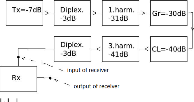
Fig.4 Block diagram of power losses
Specifications from manufacturer tells us that the receiver sensitivity is -150dBW. Sensitivity is a value that indicates how much we put stress or performance of the receiver input to achieve a desired output signal / noise ratio. After adding up the individual power losses get get total loss of signal attenuation at = -155dBW. Result of calculations is than similar like number given by manufacturer of used device.
Conclusion
In this paper described basic function and physical principles that form the basis for understanding how the non-linear junction detector works. Applied these physical principles in calculating the general power characteristics and compared them with actual parameters from manufacturers of NLJD. Summarized and described the basic technical parameters which can be guide in the selection of different types of detectors. Non- linear junction detectors has an important role in the technical surveillance counter measures (TSCM). Main advantage of NLJD ability search tapping devices which are not active and does not transmitting any signals, which radio finding methods could detect. This ability has no other technical devices for search wiretaps at all.
References
- TKOTZ, Klauz. Přířučka pro elektrotechniky. 2. české. Praha : Ben, 2001. 562 s. ISBN 80-86706-00-1.
- MAŤÁTKO, Jan. Elektornika. 6. české. Praha : Idea servis, 2005. 327 s. ISBN 80-85970-49-x.
- ŽALUD, Václav. Moderní radioelektronika 1.vyd. Praha : BEN, 2000. ISBN 80-86056-47-3
- NR-900EMS uživatelský manuál pro detektor nelineárních přechodů [online]. Moskva : Hotta, 2009 [cit. 2010-05-19]. Dostupné z WWW:
detekor.ru - NJE-4000 ORION [online]. 2004 [cit. 2010-05-19]. Dostupné z WWW:
http://www.tscm.com/orion.html

